BeamClamp BL Flange Clamp
- Jump To:
- Photos/Drawings
- Product FAQs
- Technical Specs
Overview
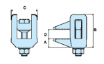
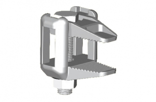
The BL is used for clamping steel directly together without the need for a location plate. Typical applications would be clamping two steel sections of the same width running parallel or for clamping down pressure vessel lids. It can also be used with clips and brackets underneath the nut and washer side for connecting conduit or even pipe work. The clamp is tested for tensile and lateral loads, please see data sheet below. The BL part is specifically designed to grip the head of a bolt or nut which means the clamp can always be connected by using a single wrench. The central bolt can be replaced with other threaded items such as threaded rod, eyebolts or J-bolts to provide a suspension element.
- Only requires one tool for installation
- Hot Dip Galvanized to BS EN ISO 1461
- Extensive clamping range
- Can accommodate clips/brackets
- Tested for Tensile and Lateral Loading
Product FAQs
What are the most common applications for the BL Clamp?
Answer: The BL Clamp is used for securing two steel sections of the same width together without a location plate, it is used for securing temporary props and can be used for hanging building services from.
Is the BL available with and without the bolt?
Answer: Yes. The BL Clamp can be purchased as an assembled item including a setscrew, nut and washer or with the two clamping elements separately. The assembly will be used for clamping steel directly together or with a bracket under the nut and the two piece option would generally be used with threaded bar to achieve a drop support for pipework or other building services.
What is the Clamping range of the BL?
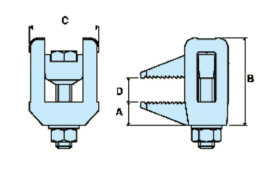
Answer: The BL design allows it to clamp down to almost any thickness of steel and a maximum given as D in the technical table.
Is the BL tested for backwards pull off?
Answer: Yes. The BL Clamp is tested for backwards pull off loads as it is sometimes used with brackets that connect to supports that would apply this type of loading. It is also tested for tensile at the centre of the bolt/threaded bar and at the nose to simulate it clamping at two sides of a connection.