• Contact Us
  • GBR
  • Call Us: +44 (0) 1384 632 188

Fast-Fit

Overview

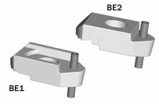
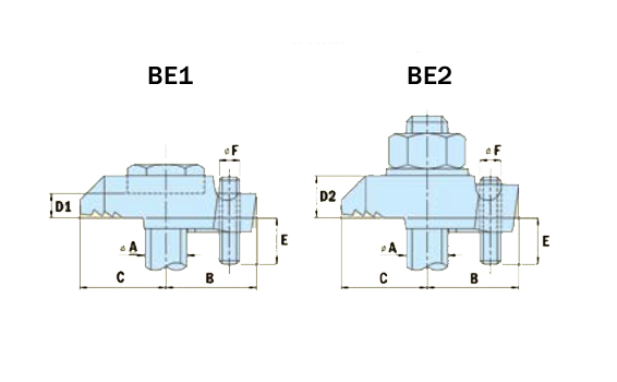
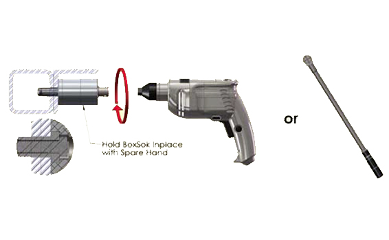
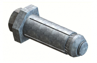
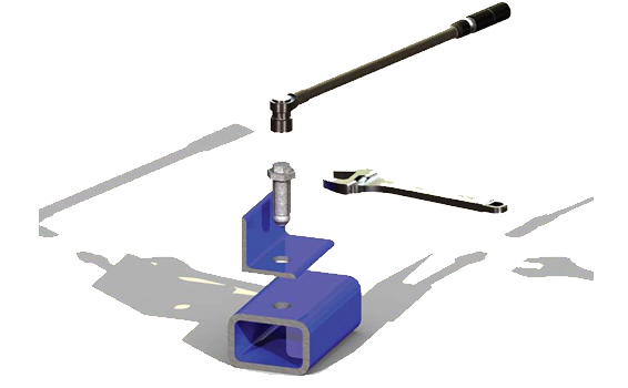
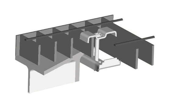
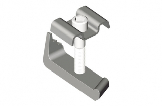
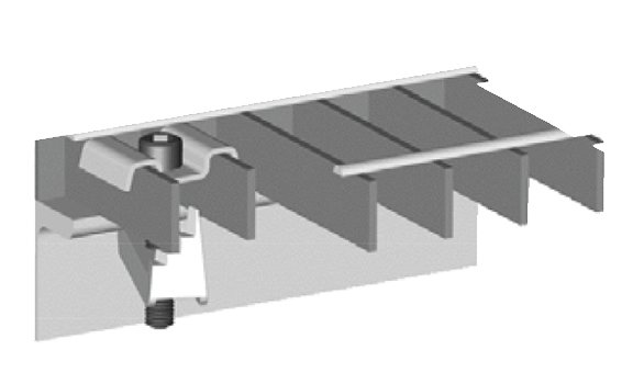
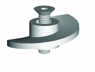
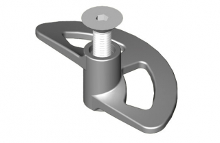
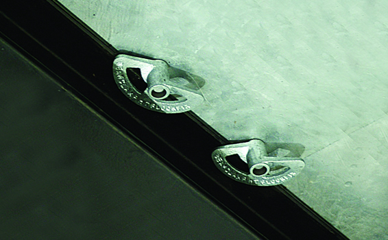
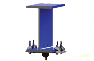
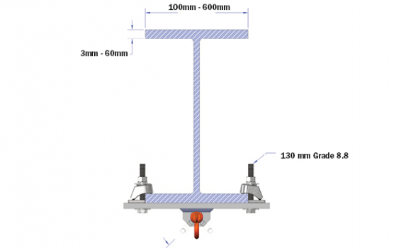
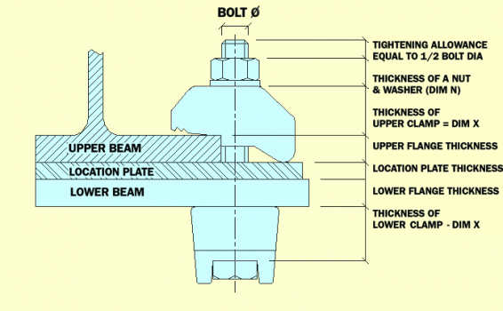
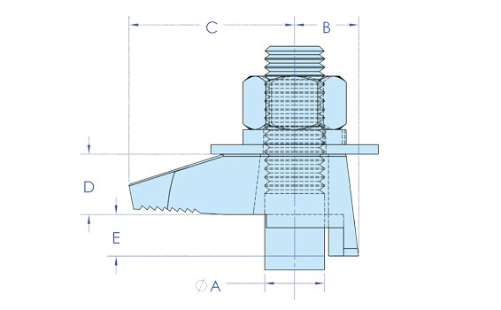
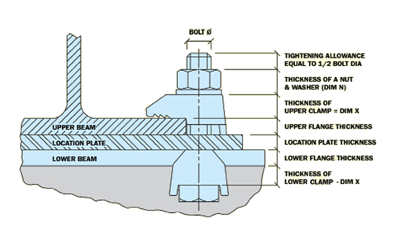
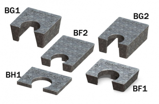
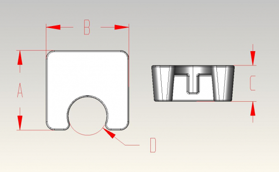
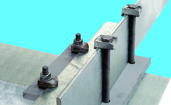
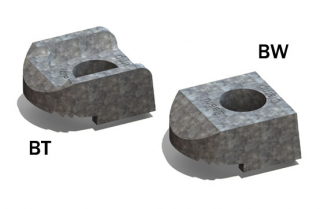
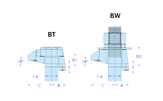
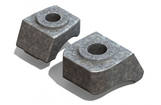
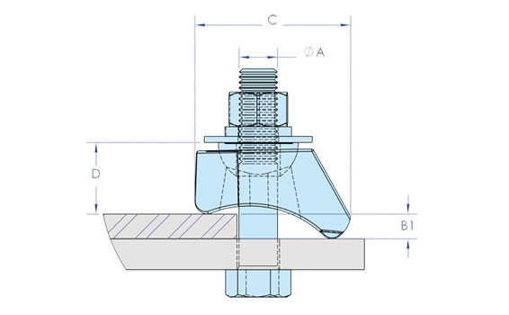
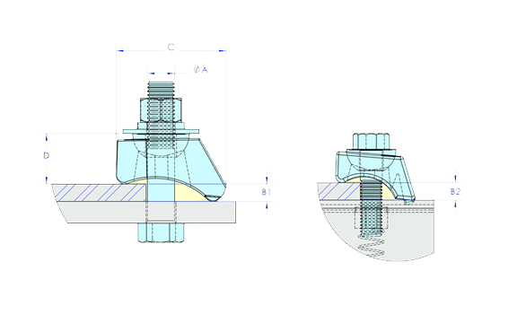
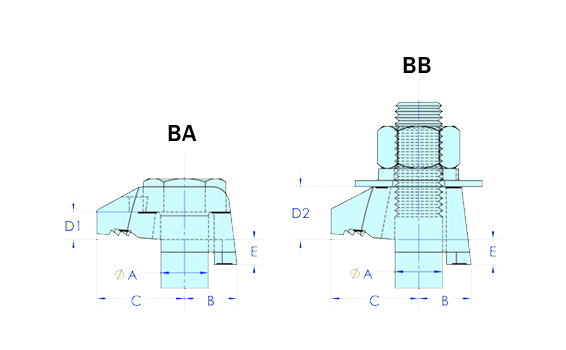
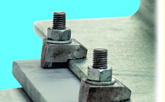
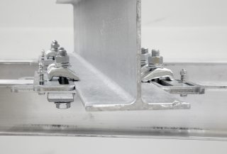
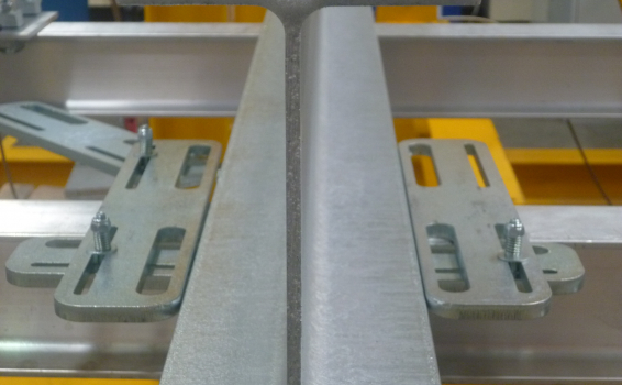
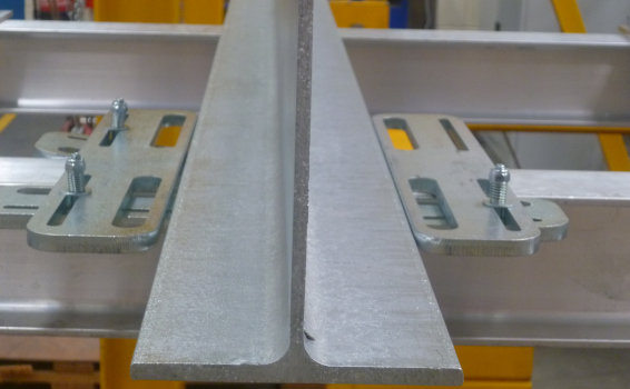
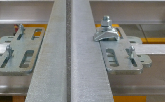
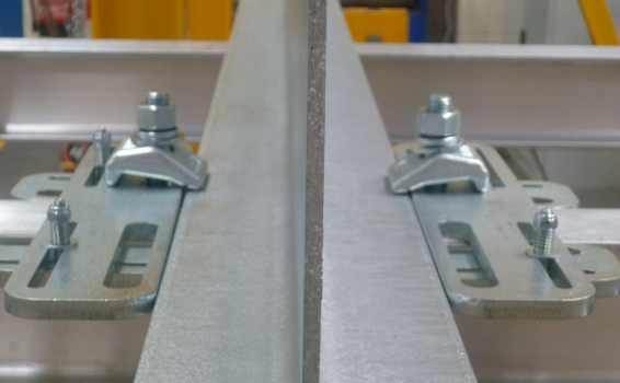
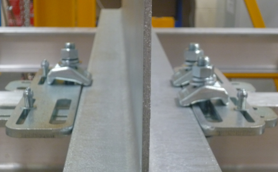
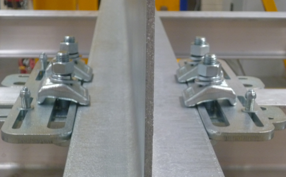
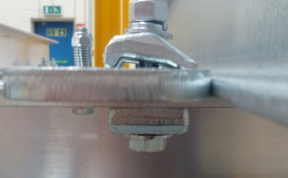
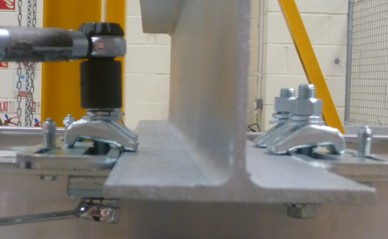
Fast Fit is an off the shelf engineered clamping solution to connect two steel sections together without the need for onsite drilling or welding. All you need to secure two sections together comes in one box. The system comprises a frame which wraps around the edges of the sections and slides into place to provide a position for the clamps to be secured. The system allows for varying angles that can be easily achieved by sliding the beams relative to each other. The Fast Fit system delivers a guaranteed connection everytime without the need for on-site testing or relying on the skills of the installer. No removal of the protective coatings on the existing steel or holes is needed to make a connection. All that is required to complete a connection are simple hand tools and semi-skilled labour.  Watch this video to see how quick and easy the Fast Fit system is to install.

  • No drilling or welding of existing or new steel
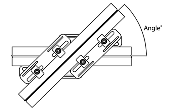
  • Allows for varying cross over angles
  • Guaranteed Safe Working load
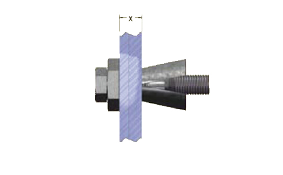
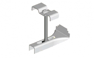
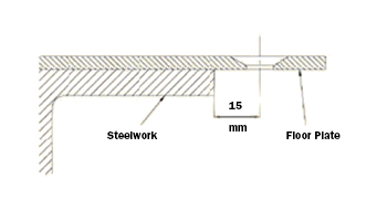
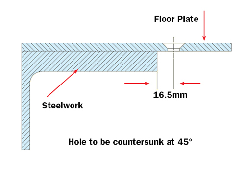
  • Flush connection between both steel sections
  • Independently load tested

Product FAQs

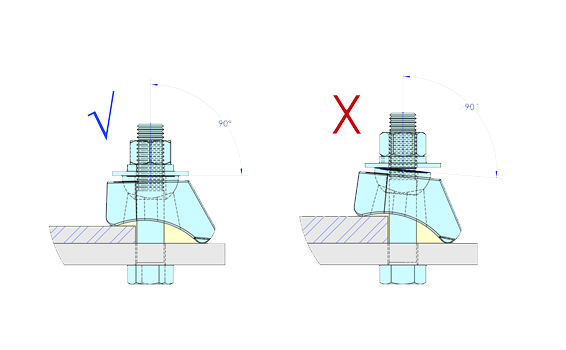
Can Fast Fit connect steel sections at angles other than 90 degrees?

Answer: Yes the Fast Fit system can allow for angle cross overs of up to 45 degrees but this depends on the widths of the steel that is being connected. Please see technical table for the widths and angles that can be achieved.

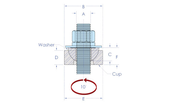
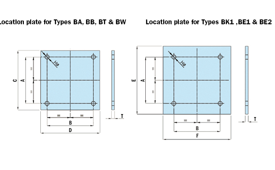
Is a location plate required with Fast Fit?

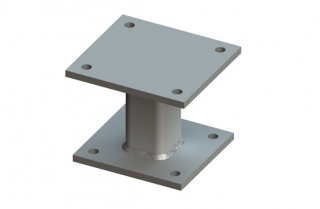
Answer: No the Fast Fit system wraps around the two sections of steel that can sit flush against each other.

How long does it take to install Fast Fit?

Answer: Fast Fit takes less than five minutes to install, see the video on the resources section of this website.

BeamClamp Components Type BE1 and BE2

Overview

The BE1 and BE2 feature a socket screw at the back to provide adjustment for varying steel thicknesses. They are the ideal choice when flange thicknesses are unknown or change on a project as they eliminate the need for packing pieces up to their maximum adjustment (Dim E). Once this maximum is exceeded our BF2 and BG2 packers can be used to increase the clamping range. Please note the BE1 and BE2 are not suitable for steel flanges with tapers greater than 5 degrees.

  • Hot Dip Galvanised BS EN ISO 1461
  • Manufactured from Ductile Iron to BS EN 1563
  • 5 to 1 Factor of Safety
  • Lloyds Register approved
  • Socket screw adjustment

The Safe Working Loads are based on assemblies tested in typical conditions

BoxSok Rapid Assembly Tool

Overview

The BoxSok Installation Tool is a rapid, unique assembly tool for the BoxBolt. This specially designed socket holds the hexagon shoulder on the body to stop rotating while allowing the inner socket to tighten up the core bolt. The core bolt draws the cone up inside the slotted body of the sleeve and expands the individual fins inside the connection. The BoxSok eliminates the need for two tools to install the BoxBolt; this considerably speeds up the installation process and also reduces the risk of trapping hands between two tools. The BoxSokTM device is available to suit all BoxBolt diameters.

BoxBolt Cavity Solutions

Overview

BoxBolt is a fully tested and approved blind connection solution for connecting to hollow section steel or where access is restricted to one side only. The BoxBolt is suitable for use with rectangular, square and even circular hollow sections. The BoxBolt features a hexagon head design to aid installation with a standard wrench. It allows it to be installed with our unique BoxSokTM installation tool for when installation time needs to be kept to an absolute minimum.

The BoxBolt is available in three finishes; Zinc Plated for the less aggressive environments, Hot Dip Galvanized for the more aggressive environments, and Stainless Steel for the most demanding of applications. These finishes combined with three lengths of BoxBolt make it extremely flexible to suit its environment and application. The BoxBolt is CE marked and approved for use by Lloyds Register (LR) type approval, to give the specifier and user total confidence.

Materials

  • Mild steel to BS EN 10083 Grade 1.1151
  • Stainless steel to BS EN 10088 Grade 1.4401

Finishes

  • Zinc plated to BS EN 12329 : Class Fe//Zn8//A
  • Hot Dip Spun Galvanized to BS EN ISO 1461

The BoxBolt is often used on high profile projects where the aesthetics of the building are essential. It is for this reason the BoxBolt can be adapted to suit the requirements of the Client and the Architect to make the connection pleasing to the eye.

Certifications


BoxBolt is CE certified in compliance with Regulation 305/2011/EU of the European Parliament and of the Council of 9 March 2011 (the Construction Products Regulation or CPR). BOXBOLT is also approved for use by Lloyds Register (LR) type approval.

Declaration of performance

Declarations in all languages are available for download here

Hemispherical Cups and Washers - BV1 and BU1

Overview

  • Allows a swing of 10° in all directions
  • Prevents the need to bend threaded rod
  • Provides pivotable element for adjustment

The hemispherical washers (BU1) and cups (BV1) provide a pivotable action when used with threaded rod. They allow a 10 degree swing in all directions from vertical and when used in pairs can provide a locked connection. Typical applications would be connecting to a roof rafter where the threaded rod needs to be hanging perpendicular to the floor or for making a ball socket on the legs of air conditioning support frames to allow adjustability for sloping roofs.

Grating Clip

Overview

The GRATING CLIP is the most common style of clip used for clamping down open steel flooring. It provides a quick and cost effective method of clamping. It is Hot Dip Galvanized and comes as standard with a top bracket to suit 30 to 41mm ctrs grating bars.

GrateFix

Overview

  • Mechanical Galvanized Malleable Iron
  • Stainless Steel Grade 304 and 316
  • Easily installed from the top side only
  • No drilling, tapping or welding required
  • Allows easy repositioning or lifting of grating
  • No special tools or skilled labor required
  • No access to the underside required
  • Tested for vibration conditions at TÜV

GRATEFIX is a heavy-duty clamp that allows open floor grating to be clamped to the supporting steel from the topside only. The Gratefix features a cast bottom piece that provides additional strength to clamp on to the steel flange. The Gratefix is available in several different styles to suit the grating dimensions and the application. A mechanical galvanized M10 version is available with a symmetrical top bracket to suit 30mm ctrs grating or with an offset bracket to suit 30 to 41mm ctrs grating. The M08 version is also available in grade 304 and 316 stainless steel with a top bracket to suit 30 ctrs.

Option 1:

Pressed Top Bracket – Stainless Steel to EN 10088 Grade 1.4301 (AISI 304)
Cast Bottom Bracket – Stainless Steel to ASTM A743 Grade CF-8 (S30400)

Option 2:

Pressed Top Bracket – Stainless Steel to EN 10088 Grade 1.4401 (AISI 316)
Cast Bottom Bracket – Stainless Steel to ASTM A743 Grade CF-8M (S31600)

Option 3:

Pressed Top bracket – Material: Mild steel to EN 10025 grade S275
Cast Bottom Bracket – Material: Malleable iron to BS 1562: Grade EN GJMB-300-06
Both finished in: Mechanical Galv to ASTM B695

FloorFix

Overview

The FloorFix is designed for securing chequer/durbar plate to the supporting steelwork without the need for on site drilling or welding of the floor plate and supporting steel structure.  It allows the connection to be made from the top side only using a basic allen key wrench.  It can be easily lifted for maintainence purposes and re-set to its original position within minutes.  The FloorFix solution can be used anywhere without the need for specialist drilling/welding equipment or the need for expensive access equipment to get to the underside.   The FloorFix is also tested at TUV for vibration conditions and providing the countersunk screw is tightened to our recommended torque then the connection is guaranteed not to come loose.

  • Installation from one side only
  • Manufactured from Ductile Iron
  • Hot Dip Galvanized
  • Allows for easy maintenance
  • Tested at TUV for vibration conditions

FloorFix HT

Overview

FLOORFIX HT has been developed following customer feedback to provide a clamp with increased functionality to suit a wider range of applications. Floorfix HT is designed to clamp flooring plate to supporting steel from the topside only without the need for time consuming on-site drilling, tapping, bolting or welding. It works on a cam mechanism that can be operated using a basic hexagon key drive.

Floorfix HT is so named because it allows steel erectors a high degree of tolerance. It retains all the benefits of our widely renowned original design but it is far more user friendly. Floorfix HT allows for floor plates to be connected to new steel that is erected within +/- 6mm of its intended position. It is capable of connecting to steel flanges from 3 to 25mm without the need for additional packing pieces.

  • Allows for +/- 6mm construction tolerance
  • Can clamp up to 25mm thick steel as standard
  • Hot Dip Galvanized finish as standard
  • Easily installed from the top side only
  • No drilling, tapping or welding required
  • Allows easy repositioning or lifting of floor plate
  • No special tools or skilled labor required
  • No access to the underside required
  • Tested for vibration conditions at TÜV

Floorfix HT has been tested for vibration conditions to simulate the most common applications where the clamps would be used, e.g. walkways, machine shops and press shops. Please ask our technical department for a copy of the certificate, should you require this.

FloorFix HT Installation Instructions

Step 1 Assemble the Floorfix HT to the underside of the floor plate making sure the markings “THIS WAY UP” are facing the underside. Loosely tighten the bolt making sure the flat edge of the clamp is in line with the edge of the steel it is going to connect to.

Step 2 Lower the plate in to position over the supporting steelwork.

Step 3 Once the floor plate is in the desired position, rotate the countersunk bolt one full turn counter-clockwise.

Step 4 Tighten the countersunk screw until the plate is secured. For guaranteed performance, use the recommended tightening torques given in our technical tables.

Note 1 We recommend using the M12 version when vibration conditions are incurred as this can be tightened to a higher torque.

Note 2 If the steel being connected to is thicker than 25mm then we can supply packers and a longer bolt to increase the clamping range.

BeamClamp Rigging Clamps - KRC062

Overview

The Adjustable Rigging Clamp is a self adjusting, ready to install rigging clamp capable of safe working loads of up to 22.2kN. The shackle connection allows loads to be applied up to 45°. The Adjustable Rigging Clamp can accommodate a variety of flange widths and thickness and is installed without the need for any drilling or welding to the support beam.

The Adjustable Rigging Clamp is available in five (5) standard sizes to accommodate any flange width from 100 to 600mm.

The Adjustable Rigging Clamp is designed to accommodate the safe working load not to exceed 22.2kN.

Note: Custom designed rigging and lifting points are available. Please contact Kee Safety for more information.

BeamClamp Location Plates and Bolt Lengths - BY

Overview

Note: Cap/End plate thickness will vary based on the design code followed, the flange width of the applicable beam and the type of load acting on the connection.

Please contact a structural engineer for further details.


BeamClamp Packing Pieces for BY Clamps

Overview

This range of packing pieces are designed to provide support to the underside of type BY clamps to ensure they clamp at 90 degrees to the steel and provide a flat surface for the bolt head or nut to be tightened down on to. These can be used in various combinations with the two tail lengths of BY clamps to achieve the best clamping position.

The Type BY can be used in a variety of applications and our design team will be pleased to configure a connection specific to your requirements.

Beamclamp Component Type BB Long Nose (BBLN)

Overview

The BB Long Nose is very similar to our standard type BB but with an extended nose. This distributes more contact on the flanges of parallel beams providing contact closer to the web. Packing pieces BH1, BF1 and BG1 can be used with this product to make it fit to various thickness’s of steel at 90 degrees.

  • Hot Dip Galvanized to BS EN ISO 1461
  • Manufactured from Ductile Iron to BS EN 1563
  • 5 to 1 Factor of Safety
  • Independently tested

BeamClamp Components Type BY and BYP

Overview

The Type BY clamp is designed for High Friction and Tensile applications that exceed the capacities of the standard BeamClamp products. It features a recessed top that prevents the head of the bolt from rotating during installation therefore requires the use of only one wrench. The Type BYP washer can be used to fill in the recess of the Type BY to provide a flat surface for a washer and nut. This also allows the Type BY clamps to be used together in beam to beam connections. The full width tail of the BY allows for use with slotted holes for greater diversity in applications.

  • Hot Dip Galvanized to BS EN ISO 1461
  • Manufactured from Ductile Iron to BS EN 1563

The BY recess is suitable for the hexagonal head of Grade 8.8 and 10.9 bolts. The Type BYP may be used to fill in the recess allowing for any grade bolt or nut to be tightened down to its surface.

Product FAQs

Why is the BY Clamp capable of such high frictional loads?

Answer: The BY Clamp has much larger sections than our standard clamps which allow it to be tightened up to much higher torques. This increases the clamping force considerably onto the steel and therefore increases the frictional slip capacity. The BY can be used with grade 8.8 or 10.9 bolts and for increased frictional capacity A490 bolts and apply a higher torque.

What is the BYP used for?

Answer: The BYP is used to fill in the recess of the BY and convert it to a flat top clamp. This allows two BY’s to be used together and only one wrench to tighten the connection.

What is the Frictional failure mode?

Answer: The frictional failure mode is when the connection is measured to have moved 1mm or 0,039” from its original position. The safety factor of 2 to 1 is then applied to this load, therefore, the test load we publish is at half that of the point where the connection even moves 1mm.

Can I use packing pieces with the BY?

Answer: Yes, our BF3,BF4 and BH2 packing pieces are specificall designed for use with our BY. A calculation chart is available at our resources section under “Specifying Beamclamp”, this shows what tail lengths and packing pieces are required.

BeamClamp Location Plate and Spacers

Overview

The location plate is an important part of a BeamClamp assembly. It provides support for the rear of the BeamClamp to react against while the front of the product clamps down on to the steel. The hole centers are designed to suit the widths of both the upper and lower members and to ensure that the clamps are located as close to the edge of the steel as possible.

Location plates can be fabricated to suit a variety of applications with different angles of cross over and gaps between sections. We will be happy to assist, free of charge, with detailing these plates for your individual applications.

Product FAQs

Why do I need a location plate?

Answer: The location plate is manufactured to suit the size of steel it is connecting together and therefore ensures that the clamps are securely up against the steel flange and are clamping onto the steel. It also stops the clamps from being able to fall off backwards.

Can I drill my new steel and remove the need for a location plate?

Answer: Yes. If the option to drill the new steel that is being secured to the existing steel is possible then the need for a location plate can be removed. This will mean though that adjustability for the connection will only be possible in one direction. With a location plate the connection is totally flexible in both axis for adjustment which can be very useful on site.

What finishes do the location plate come in?

Answer: Our standard plates are supplied with a primer finish as generally they are used internally and this is enough to stop them corroding. We can however provide them in any finish for other applications this just needs to be stated at the point of order.

Does the location plate come separately to the clamps?

Answer: No. The location plate will be supplied in a kit form with all the clamps, packing pieces, nuts and washers that you would need to make each connection. An Engineering drawing will also be supplied with each kit to make installation easy and safe.

BeamClamp Packing Pieces

Overview

Our range of packing pieces is designed to provide support to the underside of our clamps to ensure they clamp on to the steel at the correct angle. We have a series of short packers designed for the BA, BB, BT and BW clamps and a long series for the BE1, BE2 and BK1 clamps that reach further back on to the supporting steel. The packers can be used in combination with the clamping range of the clamp to ensure a correct connection. See our selection charts for the correct combinations for different steel thicknesses.

Product FAQs

Is there a maximum number of packing pieces I should use?

Answer: No, however we always recommend that if using more than three packers that the total thickness of the physical products are checked before installation. This is due to the potential of a build up of manufacturing tolerances if using too many at once.

Is there a right way up for the packing pieces?

Answer: Yes. The writing should always face upwards when installed to ensure correct installation. This is not essential on the BH1 and BH2 packing pieces as they are totally flat but on the cast packing pieces this will ensure the flat surface is at the top to support the back of the clamp correctly.

How do I know how many packing pieces to use?

Answer: This can be quickly calculated by clicking onto our resources section under “Specifying Beamclamp”, alternatively if you need assistance please contact our technical department.

What dimension is the thickness of the packing?

Answer: The thickness of the packing is always shown as dimension A on our technical tables. This should be used in combination with the tail length or clamping range of the clamp it is being used with.

BeamClamp BL Flange Clamp

Overview

The BL is used for clamping steel directly together without the need for a location plate. Typical applications would be clamping two steel sections of the same width running parallel or for clamping down pressure vessel lids. It can also be used with clips and brackets underneath the nut and washer side for connecting conduit or even pipe work. The clamp is tested for tensile and lateral loads, please see data sheet below. The BL part is specifically designed to grip the head of a bolt or nut which means the clamp can always be connected by using a single wrench. The central bolt can be replaced with other threaded items such as threaded rod, eyebolts or J-bolts to provide a suspension element.

  • Only requires one tool for installation
  • Hot Dip Galvanized to BS EN ISO 1461
  • Extensive clamping range
  • Can accommodate clips/brackets
  • Tested for Tensile and Lateral Loading

Product FAQs

What are the most common applications for the BL Clamp?

Answer: The BL Clamp is used for securing two steel sections of the same width together without a location plate, it is used for securing temporary props and can be used for hanging building services from.

Is the BL available with and without the bolt?

Answer: Yes. The BL Clamp can be purchased as an assembled item including a setscrew, nut and washer or with the two clamping elements separately. The assembly will be used for clamping steel directly together or with a bracket under the nut and the two piece option would generally be used with threaded bar to achieve a drop support for pipework or other building services.

What is the Clamping range of the BL?

Answer: The BL design allows it to clamp down to almost any thickness of steel and a maximum given as D in the technical table.

Is the BL tested for backwards pull off?

Answer: Yes. The BL Clamp is tested for backwards pull off loads as it is sometimes used with brackets that connect to supports that would apply this type of loading. It is also tested for tensile at the centre of the bolt/threaded bar and at the nose to simulate it clamping at two sides of a connection.

BeamClamp Components Type BC1 and BD1

Overview

The types BC1 and BD1 are designed to hook over the upstanding flanges of angles or channels. They can be used together for channel to channel connections or in conjunction with our other clamping products for making angle/channel connections to other types of steel. The BC1 features a recessed top to grip a bolt head and the BD1 has a flat top to allow a nut and washer to be tightened on to it. It is suitable for use with bolts, threaded rod or other threaded items but we always recommend the use of grade 8.8 high tensile threaded items.  See the video of typical application for these products.

  • Hot Dip Galvanized to BS EN ISO 1461
  • Manufactured from Ductile Iron to BS EN 1563
  • 5 to 1 Factor of Safety
  • Lloyds Register approved

Note: These products are not recommended for frictional loads

Product FAQs

What is the recess in the BC used for?

Answer: The recess is used to captivate a hexagon head of a bolt or nut to stop it spinning and allow tightening to take place by using one wrench only.

Where can I use the BC or BD?

Answer: The BC and BD are used for securing angles and channels to other steel sections in tensile or positional applications.

Can the BC/BD be used with other BeamClamp products?

Answer: Yes. The BC and BD can be combined with other BeamClamp products to secure angles and channels. Typically the BC (Recessed) would be used with a BB,BK or BW (Flat top) Clamp and the BD with a BA or BT Recessed Clamp in combination.

What approvals are available for the BC/BD?

Answer: The BC/BD are approved for use in tensile or positional applications by Lloyds Register Type Approval.

BeamClamp Components Type BT and BW

Overview

The types BT and BW are specifically designed with a 10 degrees sloping nose. This sloping nose makes them ideal for clamping on to tapered steel such as IPE's or crane rail sections. The type BT has a recessed top to captivate the head of a grade 8.8 setscrew or bolt. The type BW has a flat top to allow a nut and washer to be tightened down on it. Both clamps are available with two tail lengths, 1 or 2 (dim E). This should be as near to the thickness of steel it is clamping to or slightly less if an exact match is not possible. Packing pieces BF1, BG1 and BH1 can be used in combination with the tail length to achieve a match to the steel flange. The types BT and BW can also be used on their own if one piece of the steel has been pre-drilled. To simplify the selection of tail lengths and packing pieces, please see our selection tables in our resources area.

  • Hot Dip Galvanized to BS EN ISO 1461
  • Manufactured from Ductile Iron to BS EN 1563
  • 5 to 1 Factor of Safety
  • 10 degree nose

Product FAQs

What is the recess in the BT used for?

Answer: The recess is used to captivate a hexagon head of a bolt or nut to stop it spinning and allow tightening to take place by using one wrench only.

Why do the BT/BW clamps have specific tail lengths?

Answer: Our BT/BW Clamps have a specific tail length that are given as dimension E in our technical information. The tail length is used in combination with the thickness of our packing shims to ensure the clamp can connect as close to 90 degrees to the steel flange as possible. Our BT and BW Clamps have two tail lengths 1 and 2. A calculation chart is available in our catalogue or in our resources section under “Specifying Beamclamp”, alternatively if you need assistance please contact our technical department.

Do I always have to use the BT and BW together?

Answer: No. The BT or BW can be used on their own when only clamping to one steel section. In this situation the BT is generally used to ease installation as tightening can be achieved using one tool only. A BW can be used it just means two wrench’s are required for installation.

What packing pieces can I use with the BT/BW Clamps?

Answer: The BF1, BG1 and BH1 are all designed to work with the BT/BW Clamps. The packings are used to ensure the clamp is secured as close to 90 degrees onto the steel as possible.

BeamClamp Components Type BK1

Overview

The BK1 is a self adjusting clamp that consists of two parts. The main body provides a recess to allow a hemispherical washer to be seated. This allows the body to adjust between a specified clamping range and as the washer rotates it provides a flat surface for a nut. This mechanism makes the product suitable for clamping to tapered steel of up to 15 degrees. It is also extremely useful for projects where the thickness of steel may vary. The M08, M10 and M12 versions feature a tab at the back edge that can be located in the open ends of strut products, both aiding installation and preventing rotation once installed. Should the maximum clamping range be exceeded, our BF2 and BG2 packers can be used to increase it.  See this video to see an example of the BK product in action.

  • Hot Dip Galvanized BS EN ISO 1461
  • Manufactured from Ductile Iron to BS EN 1563
  • 5 to 1 Factor of Safety
  • Lloyds Register approved
  • Self adjusting body style

Product FAQs

What is the benefit of using a BK Clamp?

Answer: The BK Clamp is self adjusting so it can connect to a range of steel thicknesses without the need for packing pieces (See ranges B1 and B2). The washer in the middle rotates to allow the nut or bolt head to be clamping at 90 degrees to the steel.

Can I use packing pieces with BK Clamps?

Answer: Yes. Once you have reached the maximum clamping range of the BK Clamp (Dim B1) then you can use either our BF2 or BG2 long packing pieces. These packers are slightly longer to support the back of the BK Clamp.

Why does the BK have two clamping ranges B1 and B2?

Answer: B1 is for when the clamp is used on a flat surface such as a location plate and B2 is for when the clamp is used with Strut products or within slots.

Why does the BK in M08, M10 and M12 have a tab on the back of it?

Answer: This feature allows the BK to locate into Strut products or slots and stops it from rotating out once it has been tightened into position.

BeamClamp Components Type BA and BB

Overview

The types BA and BB  are commonly used in pairs to clamp two steel sections together. The type BA has a recessed top to grip the head of a grade 8.8 setscrew or bolt. This allows a nut and washer to be tightened down on to the flat top of the BB  using one tool only. Both clamps are available with three tail lengths, 1, 2 or 3 (dim E). This should be as near to the  thickness of steel it is clamping on or slightly less if an exact match is not possible. Packing pieces BF1, BG1 and BH1 can be used in combination with the tail length to achieve a  match to the steel flange.  BA and BB  types are suitable for parallel flanges and flanges up to 8 degrees taper. They can also be used on their own if one piece of the steelwork has been pre-drilled. To simplify the selection of tail lengths and packing pieces, please see our selection charts in our resources area.  To see how the BA and BB Clamps are commonly used please view this video.

  • Hot Dip Galvanized to BS EN ISO 1461
  • Manufactured from Ductile Iron to BS EN 1563
  • 5 to 1 Factor of Safety
  • Lloyds Register approved
  • DIBt approved

Product FAQs

What is the recess in the BA used for?

Answer: The recess is used to captivate a hexagon head of a bolt or nut to stop it spinning and allow tightening to take place by using one wrench only.

Why do the BA/BB clamps have specific tail lengths?

Answer: Our BA/BB Clamps have a specific tail length that are given as dimension E in our technical information. The tail length is used in combination with the thickness of our packing shims to ensure the clamp can connect as close to 90 degrees to the steel flange as possible. Our BA and BB Clamps have three tail lengths 1,2 and 3. A calculation chart is available in our catalog or in our resources section under “Specifying Beamclamp”, alternatively if you need assistance please contact our technical department.

Do I always have to use the BA and BB together?

Answer: No. The BA or BB can be used on their own when only clamping to one steel section. In this situation the BA is generally used to ease installation as tightening can be achieved using one tool only. A BB can be used it just means two wrench’s are required for installation.

What packing pieces can I use with the BA/BB Clamps?

Answer: The BF1, BG1 and BH1 are all designed to work with the BA/BB Clamps. The packings are used to ensure the clamp is secured as close to 90 degrees onto the steel as possible.

Technical Specifications

Diagram -
Diagram -

The Safe Working Loads are based on assemblies tested in typical conditions.

Product Code Bolt Diameter Bolt Grade Bolt Length (mm)   Overall size     (mm) Flange thickness
(mm)

Flange Width (mm)

Tightening Torque
(Nm)
Tensile SWL (kN) (per 4 bolts) Friction SWL (kN) (per 4 bolts)
BCFF16 M16 8.8 130 350 x 350 3 to 27 65 to 190 150 21.19 5.08

Do not exceed the Safe Working Load (SWL) specified

The above loads use a 5 to 1 Factor of Safety

                                                                                                            Achievable Angles when using Fast Fit

    Top section Flange Width
  mm 63.5 76.2 88.9 101.6 114.3 127.0 139.7 152.4 165.1 177.8 190.5
Bottom Section Flange width 63.5 45 45 50 50 50 55 55 60 65 70 75
76.2 45 45 50 50 50 55 55 60 65 70 75
88.9 50 50 50 50 55 55 55 55 65 70 75
101.6 50 50 50 50 55 55 55 55 65 70 75
114.3 50 50 50 50 50 55 55 55 65 70 75
127.0 55 55 55 55 55 55 55 55 65 70 75
139.7 55 55 55 55 55 55 55 55 65 70 75
152.4 60 60 60 60 60 60 60 65 65 70 75
165.1 65 65 65 65 65 65 65 65 65 70 75
177.8 70 70 70 70 70 70 70 70 70 75 75
190.5 75 75 75 75 75 75 75 75 75 75 80