BoxBolt Cavity Solutions
Overview
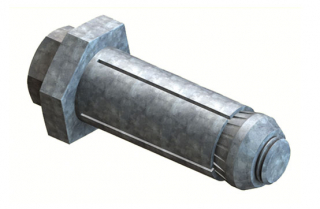
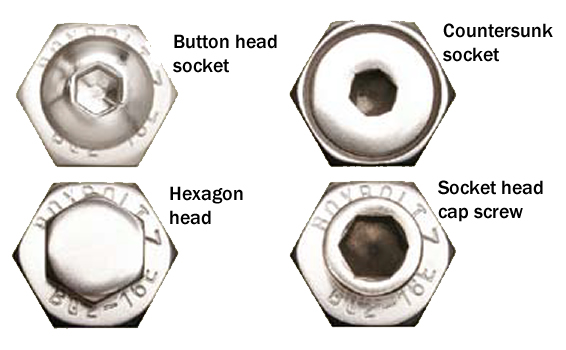
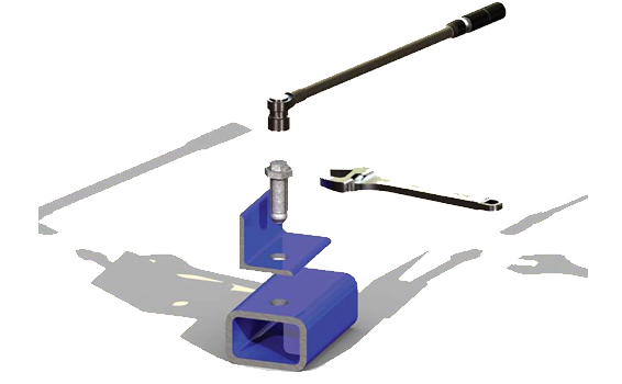
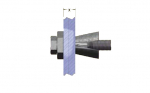
BoxBolt is a fully tested and approved blind connection solution for connecting to hollow section steel or where access is restricted to one side only. The BoxBolt is suitable for use with rectangular, square and even circular hollow sections. The BoxBolt features a hexagon head design to aid installation with a standard wrench. It allows it to be installed with our unique BoxSokTM installation tool for when installation time needs to be kept to an absolute minimum.
The BoxBolt is available in three finishes; Zinc Plated for the less aggressive environments, Hot Dip Galvanized for the more aggressive environments, and Stainless Steel for the most demanding of applications. These finishes combined with three lengths of BoxBolt make it extremely flexible to suit its environment and application. The BoxBolt is CE marked and approved for use by Lloyds Register (LR) type approval, to give the specifier and user total confidence.
Materials
- Mild steel to BS EN 10083 Grade 1.1151
- Stainless steel to BS EN 10088 Grade 1.4401
Finishes
- Zinc plated to BS EN 12329 : Class Fe//Zn8//A
- Hot Dip Spun Galvanized to BS EN ISO 1461
The BoxBolt is often used on high profile projects where the aesthetics of the building are essential. It is for this reason the BoxBolt can be adapted to suit the requirements of the Client and the Architect to make the connection pleasing to the eye.
Certifications

BoxBolt is CE certified in compliance with Regulation 305/2011/EU of the European Parliament and of the Council of 9 March 2011 (the Construction Products Regulation or CPR). BOXBOLT is also approved for use by Lloyds Register (LR) type approval.
Declaration of performance
Declarations in all languages are available for download here
Technical Specifications
Select the type of finish you require on the BoxBolt by replacing the “_ “ in the code with a Z for zinc plated, a G for Hot Dip Galvanized or an S for Stainless Steel.
Example: BQ2G12 is a 1/2” BoxBolt size 2 in Hot Dip Galvanized Finish.
| Part Number & Description |
Dimensional Information |
Load Information |
Product
code |
Bolt
Dia
|
Size
|
Setscrew
Length
|
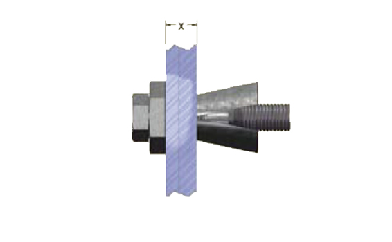
Clamping range (X
|
Across Flats of
Shoulder
|
Shoulder thickness
|
Dim A
|
Dim B
|
Hole size
Dia
|
Torque
|
Galvanised / Zinc Plate
|
Stainless Steel
|
| |
|
|
|
Min Max
|
(mm)
|
(mm)
|
(mm)
|
(mm)
|
(mm)
|
(Nm)
|
Tensile (kN)
|
Shear (kN)
|
Tensile
(kN)
|
Shear
(kN)
|
| BQ1Z06* |
M06
|
1
|
45
|
4
|
24
|
17
|
5
|
30
|
11
|
11 +1.0, -0.25
|
19
|
5.71
|
16.21
|
/
|
/
|
| BQ1_08 |
M08 |
1 |
50 |
5 |
26 |
22 |
6 |
35 |
13 |
14 +1.0, -0.25 |
25 |
12.86 |
21.07 |
13.29 |
26.14 |
| BQ2_08 |
M08 |
2 |
70 |
18 |
46 |
22 |
6 |
35 |
13 |
14 +1.0, -0.25 |
25 |
12.86 |
21.07 |
13.29 |
26.14 |
| BQ3_08 |
M08 |
3 |
90 |
30 |
66 |
22 |
6 |
35 |
13 |
14 +1.0, -0.25 |
25 |
12.86 |
21.07 |
13.29 |
26.14 |
| BQ1_10 |
M10 |
1 |
50 |
5 |
23 |
24 |
7 |
40 |
15 |
18 +1.0, -0.25 |
45 |
24.07 |
37 |
21.7 |
47.07 |
| BQ2_10 |
M10 |
2 |
70 |
18 |
43 |
24 |
7 |
40 |
15 |
18 +1.0, -0.25 |
45 |
24.07 |
37 |
21.7 |
47.07 |
| BQ3_10 |
M10 |
3 |
90 |
35 |
63 |
24 |
7 |
40 |
15 |
18 +1.0, -0.25 |
45 |
24.07 |
37 |
21.07 |
47.07 |
| BQ1_12 |
M12 |
1 |
55 |
5 |
25 |
26 |
8 |
50 |
18 |
20 +1.0, -0.25 |
80 |
29.43 |
48.29 |
30.64 |
59.86 |
| BQ2_12 |
M12 |
2 |
80 |
20 |
50 |
26 |
8 |
50 |
18 |
20 +1.0, -0.25 |
80 |
29.43 |
48.29 |
30.64 |
59.86 |
| BQ3_12 |
M12 |
3 |
100 |
40 |
70 |
26 |
8 |
50 |
18 |
20 +1., -0.25 |
80 |
29.43 |
48.29 |
30.64 |
59.86 |
| BQ1_16 |
M16 |
1 |
75 |
5 |
35 |
36 |
9 |
55 |
20 |
26 +2.0, -0.25 |
190 |
52.29 |
88.21 |
57.07 |
108.57 |
| BQ2_16 |
M16 |
2 |
100 |
30 |
60 |
36 |
9 |
55 |
20 |
26 +2.0, -0.25 |
190 |
52.29 |
88.21 |
57.07 |
108.57 |
| BQ3_16 |
M16 |
3 |
120 |
55 |
80 |
36 |
9 |
55 |
20 |
26 +2.0, -0.25 |
190 |
52.29 |
88.21 |
57.07 |
108.57 |
| BQ1_20 |
M20 |
1 |
100 |
8 |
42 |
46 |
11 |
70 |
25 |
33 +2.0, -0.25 |
300 |
92 |
145.32 |
89.07 |
181.79 |
| BQ2_20 |
M20 |
2 |
120 |
35 |
72 |
46 |
11 |
70 |
25 |
33 +2.0, -0.25 |
300 |
92 |
145.32 |
89.07 |
181.79 |
| BQ3_20 |
M20 |
3 |
150 |
65 |
102 |
46 |
11 |
70 |
25 |
33 +2.0, -0.25 |
300 |
92 |
145.32 |
89.07 |
181.79 |
The loads stated above are based on the LRFD (Load & Resistance Factor Design) method recommended by the AISC for bolted steel connections. This uses a factor of 0.75 of the ultimate load and therefore equates to a 1.33 to 1 factor of safety that we have applied to our published loads above. The overall strength of the connection is governed by the strength of material our BoxBolt is connecting into; therefore, this should be checked for structural capacity by a structural engineer.
Hole Dimensions and Positioning
| Box Bolt Size |
Dim
A (mm) |
Dim
B (mm)
|
Dim
C (mm) |
| M06 |
30 |
11 |
11 + 1.0,-0.25 |
| M08 |
35 |
13 |
14 + 1.0,-0.25 |
| M10 |
40 |
15 |
18 + 1.0,-0.25 |
| M12 |
50 |
18 |
20 + 1.0,-0.25 |
| M16 |
55 |
20 |
26 + 1.0,-0.25 |
| M20 |
70 |
25 |
33 + 1.0,-0.25 |
Minimum edge distance = Dim B + the thickness of hollow section